So, Height Generation. This was the first system I implemented completely, and for good reason. This system controls the overall shape of the generated environment, from the rocky hills to the rolling plains. The ‘Height’ portion of ‘Height Generation’ refers to the way I went about creating the shape of the environment. I generated a type of image known as a ‘height map’ to achieve it, hence the name. Obviously, it would be a good idea to get the ‘base’ of the environment down first, so I dived straight in.
The first thing I need to cover is perlin noise. If you are familiar with PCG at all, this should be a pretty obvious solution, but I need to explain it to everyone else. Perlin noise is a type of noise created by a man called Ken Perlin (shocker I know) and is extremely common in the game development sphere. It’s basically a type of ‘smooth’ noise, that creates random yet ‘rythmatic’ noise. This type of noise is perfect for natural environments, as it is extremely versatile. By generating this noise using Perlin’s algorithm and applying it to my base terrain, I was left with this:

As you can see, the 3D terrain is being sculpted by the 2D perlin noise texture, thus giving me an easy way to generate random, yet believable terrain. I went on to generate two more perlin textures with vastly different parameters before combining all three, leaving me with some very unique height generation. Here’s an extremely slowed down video of the system at work:
Well I’m not sure if you noticed, but that video of my Height Generation system was pretty gross looking. That is the reason why the next system I created covers Terrain Texture Generation. Not to be confused with my previous perlin noise texture generation, this system was designed to give the environment more color and contrast by texturing it. This system also houses my first foray into generation algorithms, so stay tuned.
The main aim of this system was the automated placement of textures at contextual locations. For example, I wanted the system to place grass textures at low altitudes and flat plains. To achieve this, I needed some specific pieces of information; the height and angle of each pixel of the terrain’s heightmap. The engine I used to develop this project, Unity, possessed some very useful functions that could supply me with that exact data with it’s GetHeight and GetSteepness methods. These methods do exactly what you’d think when supplied a heightmap pixel, thus solving my information issue.
Now it was all well and good to have the height and angle of each pixel, but I needed to design an algorithm to actually select specific textures to specific heights. This is the first one I designed, it was used to place the grass textures:
x = clamp( cosh〖g/h〗− 1.25) − clamp( s*s)/ (t/f))
Where x is grass texture transparency from 0 – 1; g is grass height lenience; h is height of the
current pixel; s is steepness of the current pixel; t is the max height of the Terrain; f is grass
flatness lenience
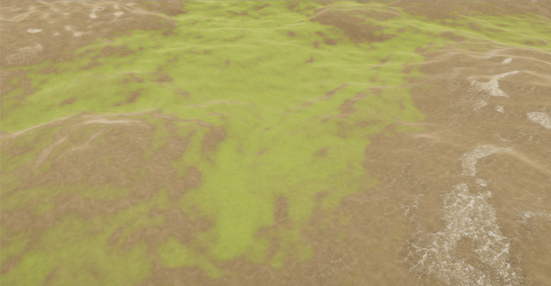
Now what this algorithm does is decide the transparency of the applied grass texture at any given pixel. If x equaled 0, I would simply skip that pixel instead of placing an invisible grass texture for performance. The algorithm allowed for fine control over how the grass texture was placed, with both g and f being two easily altered variables. Here’s an example of this algorithm in action:
![]()
As you can see, the grass texture is only being applied on lower and flatter sections of the terrain, as that is how I designed the algorithm. You can also see how the grass texture is ‘blending’ into the dirt texture as it approaches it’s maximum height/angle.
With the grass rule out of the way, I also wanted a rule to control the placement of rock textures, to give the terrain a bit more visual variety. I had to do something a bit different with this one though, as I needed the angle of a single axis at each pixel. To do this, I analysed the ‘normal’ of each pixel. In this case, the pixel’s normal refers to it’s rotation on all three axis’ (x, y and z). Here’s the algorithm I designed for that:
x = clamp((h/r^2)*cosh〖n/a〗
Where x is rock texture transparency from 0 – 1; h is the height of the current pixel; r is the
rock height lenience; n is the current pixel’s normal value on the z axis; a is the rock angle
lenience
Inverse to the grass rule, I designed this algorithm to place the rock textures at high altitudes. Like the grass rule, it returns a value between 0 and 1, letting me easily control the transparency of the texture at any given point:
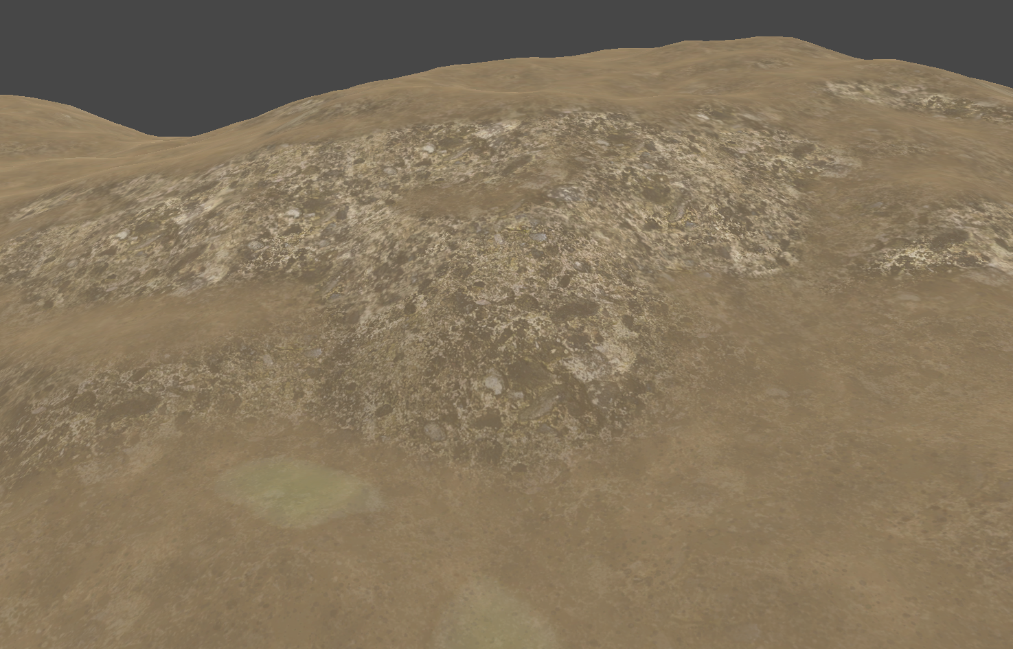
Running these two rules together at each heightmap pixel resulted in varied textures being placed all throughout my terrain. This texture placement was actually more crucial than the height generation of my previous system, as multiple systems designed after this one analyse the generated terrain textures during their own processes.
Even with those nice textures I still felt my terrain was a bit flat, so the next system I designed was Detail Generation. When I say details, I’m referring to the smaller parts of a forest environment, mainly swaying grass. This system was fairly straightforward to design and implement, as all I needed was the textures I generated in my previous system.
The way I automatically placed the details was by analysing the textures present at any given pixel of the terrain. If the alpha value (that 0 to 1 value of my texture algorithms) of the grass texture on the selected pixel was above a certain threshold, the system would place a grass detail.
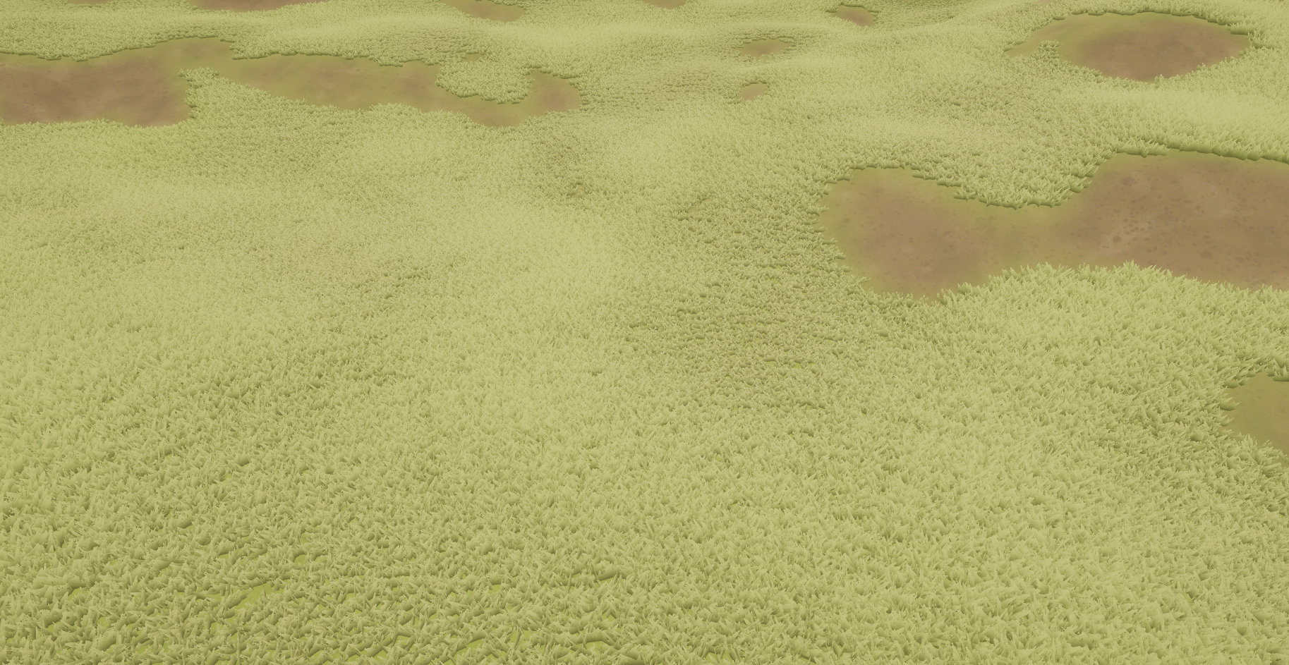
As you can see, it definitely added some depth to my environment when these details were generated. However I wanted finer control over the general placement of these details, so I implemented two variables. The first was DetailPlacementPower:

This variable would hook into the loop I used to analyse terrain pixels and would skip over pixels that weren’t a power of DetailPlacementPower. This allowed me to reduce the details placed as a whole, thus giving me the ability to run the environment on lower-end machines. The second variable implemented was DetailPerPixel.
![]()
This variable did the complete opposite to DetailPlacementPower, and (suprise suprise) increased the amount of details placed per terrain pixel. These two variables allowed me to completely control the density of the generated details, very convenient.
After I’d gotten some of the small details (heh) out of the way, my next planned system was a big one, Point Generation. This system was responsible for placing the actual objects that would populate the forest. Trees and rocks were the two main objects I chose to place around my environment, as they are both fairly common in forests.
Before getting into my implementation, I’ve got to do a small presentation on Poisson Disk Sampling. No it’s not a type of dish, it’s actually the backbone to this whole system. Poisson Disk Sampling is a way of generating random, yet structured point placement. The algorithm has three main steps:
- Create a ‘phantom’ grid for the algorithm to iterate through. Grid cells need to be sized to allow only one ‘sample’ within them.
- Place a point within the grid randomly and add it to an ‘active list’
- While the ‘active list’ is not empty, choose a random point from it and generate a specific amount of points around it. If one of those generated points is outside a specified radius around the selected point, remove all other generated points and add that one to the active list before removing the old selected point. Continue until the active list is empty.

Above is a basic implementation of Poisson Disc Sampling. As you can see, each point has been placed at random, but no point is within another point’s ‘radius’. This algorithm is extremely useful for object placement, but there is some margin of error as seen here:

I’ve highlighted the places a point COULD have been placed in red. The random nature of first place point is the cause of this, It’s not that devastating an error, but it was something I had to keep in mind moving forward.
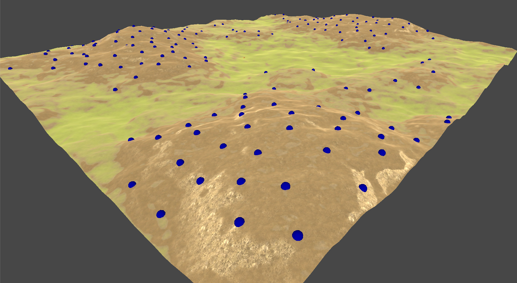
As you can see, Poisson Disc Sampling is a mighty fine placement algorithm… for 2D points. I quickly ran into the task of transforming these 2D points into 3D ones. My approach was fairly simple, I generated the points as usual, but when a point was generated I cast a ‘ray’ from above the point. This ray would cast directly downward, and would get the height of the terrain at the point’s 2D coordinates. Combining this height value with the generated 2D coordinates, I successfully converted a 2D placement algorithm into 3D:

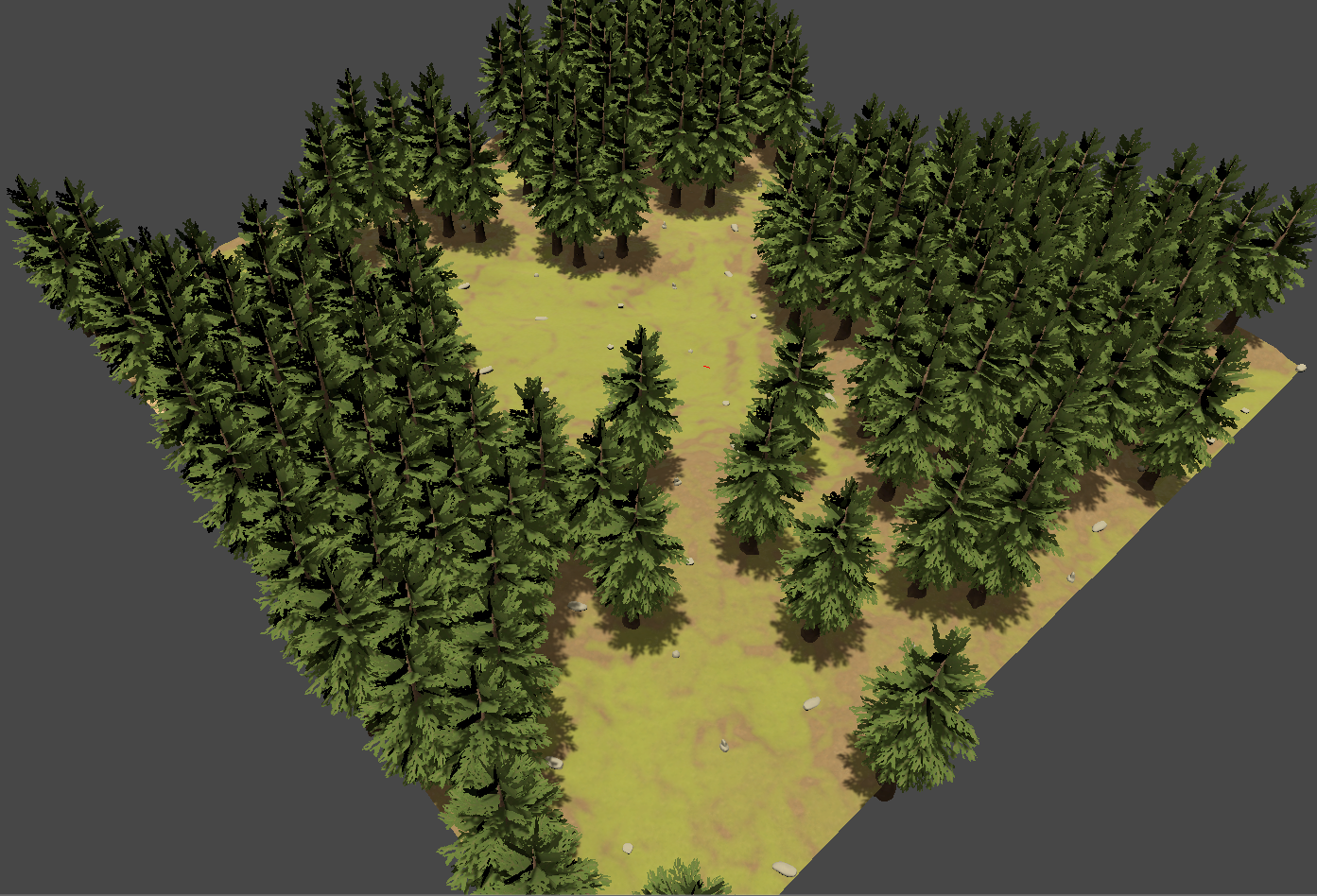
After that, I decided that I wanted rules for the point placement, similar to those of my Detail Generation system. Specifically, I wanted trees to only be placed on dirt. This was to allow some open areas in the generated forest to break up the scenery. I did this in the exact same way as my details, I sampled the alpha of the terrain texture at all the generated points to decide whether the point should be placed:
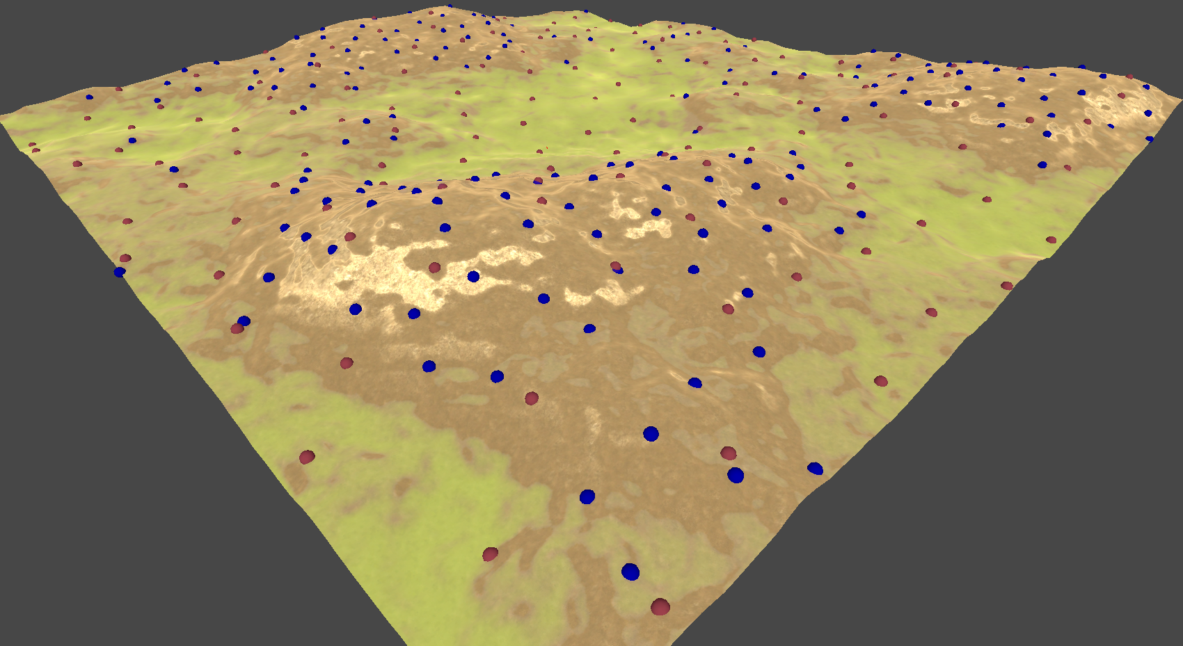
 Then I added a second Poisson Disk Sampling pass to generate points for the rocks. I didn’t care where these rocks were placed, so I didn’t implement any specific rules for them:
With the points generated, it was fairly simple to just place the wanted models at each point. To add some more randomness, I rotated the models randomly when they were placed. Here’s the end result: